Connected Components of a Polygon Mesh
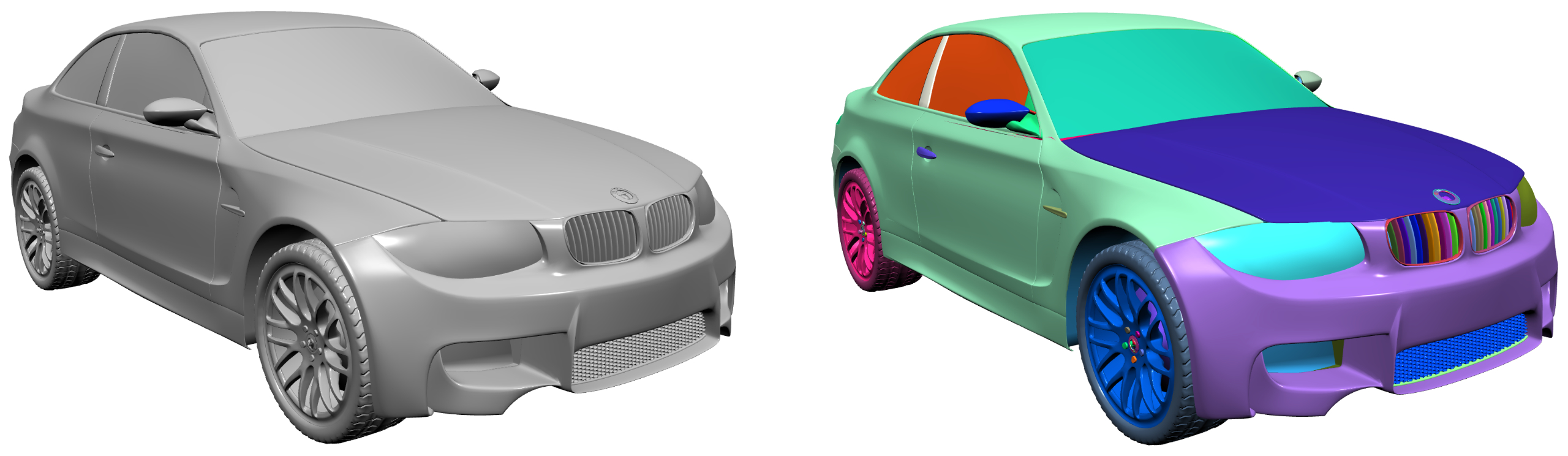
In mesh processing, we often assume ideal 2-manifold meshes consisting of a single connected component. In practice, however, meshes can be more complex: a single object may actually consist of many disconnected components, as shown in the image above.
Depending on your application, you may need to detect these components for further filtering or processing. I recently added connected component detection to PMP. This article provides a concise, practical overview of the algorithm and is also a good exercise for learning to work with meshes.
I’ll first outline the general algorithm, describe the C++ implementation, and show how to test it. I’ll also briefly demonstrate how to visualize components using color-coding. Finally, I’ll filter components for further downstream processing.
Basic Algorithm
The algorithm is based on a breadth-first traversal of the vertex graph. Starting from a seed vertex, it incrementally discovers all vertices connected to that seed. Here’s some pseudo-code:
for each vertex

  if vertex not yet visited
    mark vertex as visited
    push vertex to queue

  while queue not empty
    pop vertex from queue

    for each neighbor vertex
      if neighbor not yet visited
        mark neighbor as visited
        push neighbor to queue
Here’s an image illustrating the principle: starting from a seed vertex, all connected neighbors are visited incrementally.
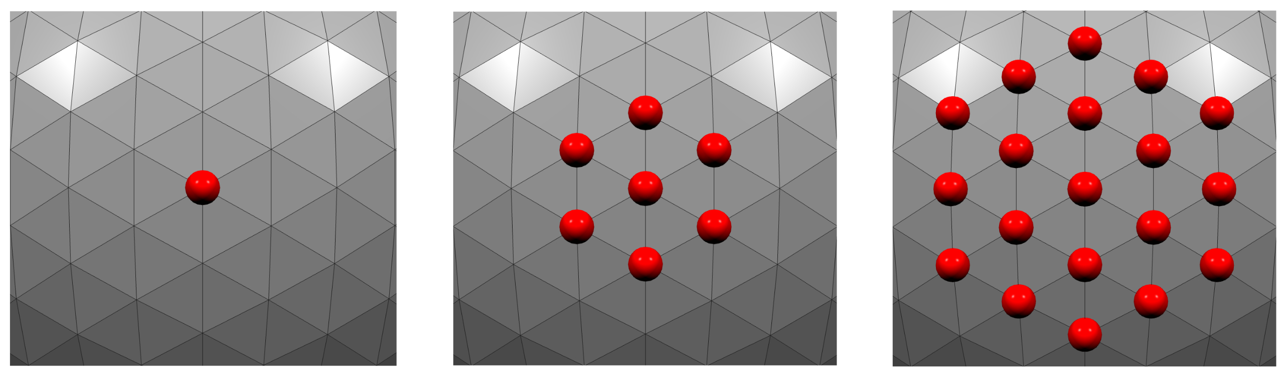
Here, connected components are defined with respect to vertex adjacency: two vertices are connected if they share an edge. In other words, components are computed on the vertex graph induced by mesh edges. Face-connected components can be computed similarly by traversing face adjacency.
C++ Implementation
Now let’s implement this in C++ using PMP. I left out some details in the pseudo-code that are essential for a practical implementation. In particular, we want to keep track of the current component index and remember which vertex belongs to which component. The function should also return the number of components so that callers can easily check if there are multiple components present. Here’s the full implementation:
int connected_components(SurfaceMesh& mesh)
{
  // add component as vertex property
  auto component = mesh.add_vertex_property<int>("v:component", -1);

  // index to track current component
  int idx = 0;

  for (auto v : mesh.vertices())
  {
    if (component[v] != -1)
      continue;

    std::queue<Vertex> vertices;
    component[v] = idx;
    vertices.push(v);

    while (!vertices.empty())
    {
      auto vv = vertices.front();
      vertices.pop();

      // visit neighboring vertices
      for (auto vc : mesh.vertices(vv))
      {
        if (component[vc] == -1)
        {
          component[vc] = idx;
          vertices.push(vc);
        }
      }
    }

    // increment component index
    idx++;
  }

  // return number of components
  return idx;
}
Note that vertices not connected to any other vertex are detected as individual connected components. This naturally follows from the algorithm being based on vertex adjacency.
Testing
Let’s verify that the algorithm works. The simplest test case is a mesh with a single component:
SurfaceMesh mesh;
auto v0 = mesh.add_vertex(Point(0, 0, 0));
auto v1 = mesh.add_vertex(Point(1, 0, 0));
auto v2 = mesh.add_vertex(Point(0, 1, 0));
mesh.add_triangle(v0, v1, v2);

auto nc = connected_components(mesh);

assert(nc == 1);
That works. Now let’s add two disconnected triangles:
SurfaceMesh mesh;
auto v0 = mesh.add_vertex(Point(0, 0, 0));
auto v1 = mesh.add_vertex(Point(1, 0, 0));
auto v2 = mesh.add_vertex(Point(0, 1, 0));
mesh.add_triangle(v0, v1, v2);

v0 = mesh.add_vertex(Point(2, 0, 0));
v1 = mesh.add_vertex(Point(3, 0, 0));
v2 = mesh.add_vertex(Point(2, 1, 0));
mesh.add_triangle(v0, v1, v2);

auto nc = connected_components(mesh);

assert(nc == 2);
Works as well. For a more practical and realistic test case I’ll generate multiple mixed polygon meshes and combine them into a single mesh. For that I need a helper function to append one mesh to another:
auto append = [](const SurfaceMesh& source, SurfaceMesh& dest) {
  std::map<Vertex, Vertex> vertex_map;
  for (auto v : source.vertices())
  {
    Vertex new_v = dest.add_vertex(source.position(v));
    vertex_map[v] = new_v;
  }
  for (auto f : source.faces())
  {
    std::vector<Vertex> face_vertices;
    for (auto v : source.vertices(f))
    {
      face_vertices.push_back(vertex_map[v]);
    }
    dest.add_face(face_vertices);
  }
};
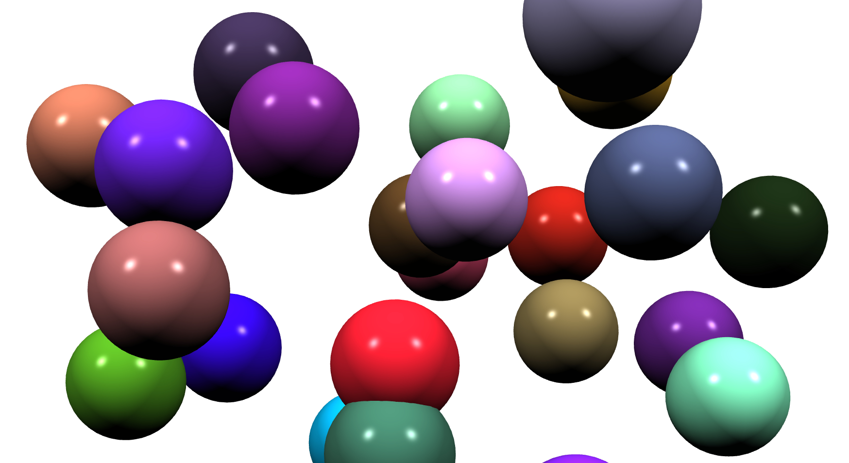
Now you can generate a few randomly placed spheres, combine them into a single mesh, and make sure to detect the right number of components:
SurfaceMesh mesh;
for (int i = 0; i < 10; ++i)
{
  Scalar x = rand() / (Scalar)RAND_MAX;
  Scalar y = rand() / (Scalar)RAND_MAX;
  Scalar z = rand() / (Scalar)RAND_MAX;

  auto sphere = uv_sphere(Point(x, y, z), 0.1, 25, 25);

  append(sphere, mesh);
}
auto nc = connected_components(mesh);
assert(nc == 10);
Visualization
If you want to visualize the individual components you can assign a color based on the component index to the mesh faces:
const auto n_components = connected_components(mesh);
auto face_colors = mesh.face_property<Color>("f:color");
auto component = mesh.vertex_property<int>("v:component");

// create a color map
std::map<int, Color> component_colors;
for (int i = 0; i < n_components; ++i)
{
  float r = (rand() / (float)RAND_MAX);
  float g = (rand() / (float)RAND_MAX);
  float b = (rand() / (float)RAND_MAX);
  component_colors[i] = Color(r, g, b);
}

// assign face colors
for (auto f : mesh.faces())
{
  // determine component index from any face vertex
  const auto v = mesh.vertices(f);
  const auto idx = component[*v];
  face_colors[f] = component_colors[idx];
}
Here we are, detecting connected components and visualizing them using color-coding:
Filtering
Depending on your application, you may want to filter the detected components based on some criterion. The approach is similar to the color-coding example above: first run component detection, then filter according to your chosen criterion. As an example, we’ll extract the largest component, using the bounding box size as a simple metric that works even for meshes with boundaries.
First, let’s split all components into separate meshes. I’m intentionally using this explicit approach for demonstration purposes and because the functionality itself might be useful in other cases.
auto split = [](SurfaceMesh& mesh) -> std::vector<SurfaceMesh> {
  const auto nc = connected_components(mesh);
  std::vector<SurfaceMesh> meshes(nc);
  auto component = mesh.vertex_property<int>("v:component");

  // one vertex map per component
  std::vector<std::map<Vertex, Vertex>> vertex_maps(nc);

  for (const auto f : mesh.faces())
  {
    // determine component from any face vertex
    const auto v = mesh.vertices(f);
    const int idx = component[*v];

    std::vector<Vertex> face_vertices;
    face_vertices.reserve(mesh.valence(f));

    for (const auto vv : mesh.vertices(f))
    {
      auto& vmap = vertex_maps[idx];

      // create vertex only once per component
      if (vmap.find(vv) == vmap.end())
      {
        Vertex new_v = meshes[idx].add_vertex(mesh.position(vv));
        vmap[vv] = new_v;
      }

      face_vertices.push_back(vmap[vv]);
    }

    meshes[idx].add_face(face_vertices);
  }
  return meshes;
};
All that’s left to do is to determine the largest component. I’m using bounding box size for simplicity, adjust accordingly if you want to check for area or volume.
// assume that mesh has several components of varying size
auto meshes = split(mesh);
int largest = 0;
Scalar max_size = -std::numeric_limits<Scalar>::max();
for (size_t i = 0; i < meshes.size(); i++)
{
  const auto size = bounds(meshes[i]).size();
  if (size > max_size)
  {
    max_size = size;
    largest = i;
  }
}
Hope this helps!